
Shop drawings
Fiber cement panel shop drawings
Fiber cement panels look right when the grid is planned and every joint has its detail. We draw the panel layout on each elevation and the details behind it: joints, flashings, fastener patterns, corners, openings and the movement joints at the floor lines, to the manufacturer's installation instructions for the panel in your spec.
- Price
- Fixed price, quoted within one business day
- Turnaround
- Agreed per building and released in sets
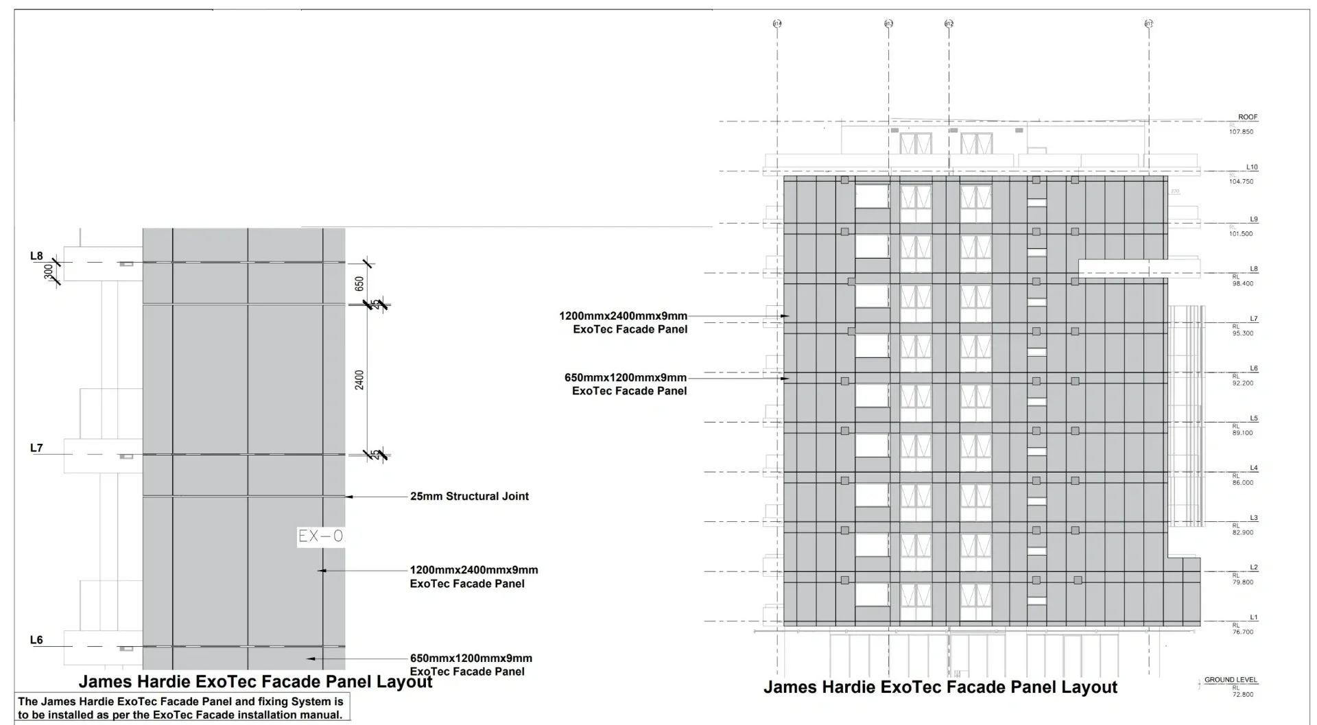
The panel grid comes first
A fiber cement panel facade is only as good as its grid. Before any detail is drawn, we set out each elevation in full panels, decide where the vertical and horizontal joints fall, and line them up with the window heads, sills and floor lines so the joints read as part of the design rather than wherever a sheet ran out. Small slivers next to openings, and joints that land just off a window jamb, are fixed on paper instead of on the scaffold.
Joints: trim, reveal or flashing
Fiber cement panel systems allow a few joint types, and the drawings must show the one your spec and the manufacturer call for. Vertical joints may be butted and caulked, covered with a batten, or left as an open reveal with a backing strip. Horizontal joints usually take a Z-flashing or a two-piece trim that laps the panel below. We draw the joint type at every location and give each one its detail, so the crew never has to guess.
Floor lines on wood-frame buildings
On multi-story wood-frame buildings, the frame shortens as the lumber dries and the load comes on, and a rigid panel fixed across a floor line can crack or buckle. Where the design team calls for a movement joint at each floor, we show it on every elevation and detail it through the panel, the furring, the insulation and the weather barrier, sized as the structural engineer or the envelope consultant specifies.
Fasteners and edge distances
Fastener type, spacing and edge distances come from the manufacturer's installation instructions and, on taller or exposed buildings, from the engineer's wind-load requirements. We put those on the drawings: the fastening pattern for the field and the edges of each panel, the distances from corners and openings, and any zone where the engineer asks for closer spacing.
Panels over rainscreen and exterior insulation
Where the panels go over a rainscreen cavity or continuous insulation, the wall section shows the layers in order: the sheathing, the weather barrier, the insulation, the furring or the clip and girt system, the cavity and the panel, with the screen at the base and the top of the cavity. The attachment is designed by the system supplier's engineer; we draw it from their data and coordinate the panel fastening with it.
Details in a fiber cement panel set
- Vertical and horizontal joint details for each joint type
- Window and door head, sill and jamb, with the flashing laps
- Inside and outside corners
- Base of wall, with the clearance to grade or roof and the cavity screen
- Floor-line movement joints
- Transitions to other claddings, storefronts and soffits
- Penetrations: vents, lights, hose bibs and conduit
Fiber cement under 07 46 46
On a commercial or multifamily job, fiber cement siding and panels are usually specified in section 07 46 46, with the weather barrier, the insulation and the flashing in their own Division 07 sections. We draft the fiber cement set so it lines up with those sections, and we can draw the whole Division 07 package when the scope is yours; see our Division 7 shop drawings page.
Drawn by a team that knows these panels
Our founder spent more than 17 years in James Hardie's technical team and wrote its ExoTec facade manual, so fiber cement panels are the system this team knows best: how the panels move, where they need support and how the manufacturers test their joints and flashings.
Questions we are asked
Do you draw HardiePanel vertical siding and other fiber cement panels?
Yes. We draw fiber cement panel systems from the major manufacturers, to the manufacturer's current installation instructions for the product in your spec. Anything the design asks for beyond those instructions is flagged, so it goes to the manufacturer or the engineer before the drawings are issued.
Can you show joints with trims, battens or open reveals?
Yes. We draw the joint type your spec and the manufacturer call for, at every location on the elevations, with a detail for each.
How do you handle movement at the floor lines?
We show the movement joint the design team specifies at each floor of a wood-frame building, and detail it through the panel, the furring, the insulation and the weather barrier.
Do you draw fiber cement lap siding too?
Yes. Lap siding, panels and the trim around them are on our siding shop drawings page; a building that mixes both gets one coordinated set.
Can the panel quantities come with the drawings?
Yes. A siding takeoff measured from the same panel layout gives the panel, trim, flashing and fastener counts for your order.
Is engineering included?
No. We draft only. Wind-load design, attachment design and any stamped drawings stay with the project engineer or the manufacturer, and we draw to their requirements.
Related services
- Division 7 shop drawingsDivision 07 shop drawings for US cladding subcontractors: fiber cement, metal and ACM panels, continuous insulation, WRB and flashing details..
- Metal & ACM wall panel shop drawingsShop drawings for metal and ACM wall panels: elevation layouts, panel schedules, wet-seal and dry-joint details, clip and girt layouts, and Revit families..
- Siding & facade panel shop drawingsSiding and facade panel shop drawings for US installers: panel layouts, joints, fasteners and trim details for fiber cement, metal and composite systems..
- Siding takeoffsSiding takeoffs for US contractors and suppliers: lap siding, panels, trim, soffit and accessories measured from your elevations, with waste shown..